Blind-spot awareness is no longer limited to premium cars. As e-bikes, electric tricycles, scooters, and compact special-purpose vehicles become more common, safety-assistance hardware is moving into lower-speed mobility platforms as well. The BD4104B-C01 radar module is designed for this trend, bringing rear blind-spot detection and warning capability into a compact board-level solution.
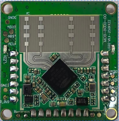
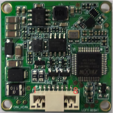
Based on the specification, the module integrates a 77GHz to 81GHz FMCW radar transceiver, 2Tx 2Rx PCB antenna array, radar signal processing, and a high-performance automotive-grade MCU. It supports CAN connectivity and warning outputs for left and right indicators, making it suitable for system-level safety integration.
1. Why Blind-Spot Radar Matters for Low-Speed Vehicles
Riders of e-bikes, scooters, motorcycles, and utility vehicles are often exposed to limited rear visibility. Mirrors and rider attention help, but they are not always enough when nearby vehicles approach quickly from the side or rear. A blind-spot radar module can continuously watch these dangerous zones and provide earlier warning to the rider or vehicle controller.
This is particularly useful in lane-change scenarios, dense city traffic, and mixed-vehicle environments where small mobility platforms share the road with larger vehicles.
2. Core Functional Strengths
The BD4104B-C01 uses FMCW radar processing, which enables distance, speed, and angle estimation for moving targets. The specification highlights wide angular coverage, high sensitivity, support for up to 16 targets, and resistance to environmental conditions such as dust, airflow, light, temperature, and humidity. These are exactly the conditions where optical-only approaches may become unreliable.
For practical vehicle integration, the module also supports CAN communication and controlled warning outputs that can directly cooperate with left and right indicator logic.
3. Detection Capability and Technical Parameters
| Parameter | Specification | Note |
|---|---|---|
| Working Mode | FMCW | Continuous-wave radar processing |
| Working Frequency | 77-81GHz | Millimeter-wave band |
| Antenna | 2Tx 2Rx | Integrated PCB antenna |
| Vehicle Detection | 40m | 10dBsm reference |
| E-bike Detection | 25m | 0dBsm reference |
| Pedestrian Detection | 15m | -7dBsm reference |
| Angle Coverage | Horizontal +/-60 deg, vertical +/-15 deg | Wide warning zone |
| Refresh Time | 100ms | Fast update |
| Working Voltage | 9V-16V | Vehicle power range |
| Module Size | 32 x 32 x 9mm | Compact installation |
4. BSD, Lane Change Assist, and Rear Collision Warning
The specification describes several practical warning functions. BSD covers blind-spot monitoring around the rear side area of the vehicle. LCA supports lane-change assistance by warning when a target approaches quickly from the adjacent rear lane. RCW adds rear collision warning logic for specific near-center rear scenarios. Together, these functions help riders avoid dangerous merging and turning decisions.
This kind of functional layering makes the module more than a raw radar sensor. It becomes a compact safety subsystem for mobility products.
5. Application Scenarios
According to the specification, target applications include low-speed passenger vehicles, lightweight motorcycles, electric tricycles, electric bicycles, scooters, self-balancing vehicles, and special-purpose machinery vehicles. These are all platforms where cost, space, and integration simplicity matter, but safety demand is rising quickly.
6. Installation Considerations
The module is intended for rear installation, typically at a height of roughly 30cm to 100cm above ground. The front cover should use non-metal material without metallic coating, and the space between the radar and cover should follow the recommended distance guidance. Mechanical alignment is also important, with azimuth and pitch tolerance kept within the specification range for best performance.
These requirements are critical because blind-spot radar performance depends not only on the RF design itself, but also on cover material, mounting angle, and installation position inside the vehicle body.
7. Conclusion
The BD4104B-C01 is a practical radar module for brands developing safer e-bikes, scooters, motorcycles, and other low-speed vehicles. With compact size, CAN-friendly integration, wide detection coverage, and dedicated safety-warning logic, it offers a clear upgrade path for mobility products that need blind-spot awareness without a large hardware footprint.
Interactive Demo
Download the Product PDF
Get the corresponding specification sheet for this article.
Interested in integrating this sensor?
Request a free sample and get technical support from our engineering team.